
SG3525 is voltage controlled PWM IC.
Features;
The main feature of sg3525 is adjustable frequency and adjustable duty cycle.
It has an onboard error amplifier.
It has an internal soft starter feature.
100hz to 500khz oscillator range
SG3525 is used in many applications.
This PWM IC is used in DC to AC inverter, DC to AC converter, Power supplies, solar inverter, and many other applications.
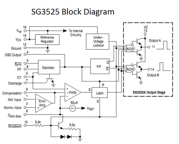
Block diagram;
 Pin Diagram:

Pin 1 & Pin 2;
Pin 1 is inverting input while pin 2 is a non-inverting pin of the onboard error amplifier. This onboard amplifier is a comparator that controls the duty cycle of PWM. When the voltage on inverting pin that is pin 1 increases the voltage than pin 2 that is non inverting pin duty cycle decreases. While when the voltage on the inverting pin decreases then the non inverting pin duty cycle increases.
Pin 3 & Pin 4;
Pin 3 is sync that is used for synchronizing IC with an external oscillator. This is used when more than 1 IC used. Pin 4 is the output of the oscillator
Pin5 & Pin6;
Pin 5 (ct) and Pin 6 (rt) are together used for setting the frequency of PWM.
Frequency formula is ;
f= 1 / CT (.7 * RT+ 3 * discharge)
Pin 7;
We can use this pin for setting the dead time of IC it means the dead time between pulses.
Pin 8 (soft starter);
It is used for starting the operation of IC softly. The capacitor that is connected with this pin and ground determines the level of the soft start process.
Pin 9(comp);
It is a compensation pin that is used with feedback to avoid the rapid change in output voltage due to load change.
Pin 10(shut down );
IF shut down pin low it will work and if shut down pin is logic high It means that it is connected with 5 volts it will remain in shut down mode.
Pin11 & Pin14:
These both pins are output pin of IC with totem pole output means if we apply these output to MOSFET there is no need of MOSFET driver.
Pin13 & Pin15:
These both pins are power pin.VC should be between 5volt to 35 volts while Vin should be 8 volts to 35 volts.
Pin 12;
It is connected with ground.
Pin 16;
It is a reference pin. It is used for setting reference through pin 1 and pin2.
Here is a diagram of SG3525 Circuit.

Features;
The main feature of sg3525 is adjustable frequency and adjustable duty cycle.
It has an onboard error amplifier.
It has an internal soft starter feature.
100hz to 500khz oscillator range
SG3525 is used in many applications.
This PWM IC is used in DC to AC inverter, DC to AC converter, Power supplies, solar inverter, and many other applications.
Block diagram;

Pin 1 & Pin 2;
Pin 1 is inverting input while pin 2 is a non-inverting pin of the onboard error amplifier. This onboard amplifier is a comparator that controls the duty cycle of PWM. When the voltage on inverting pin that is pin 1 increases the voltage than pin 2 that is non inverting pin duty cycle decreases. While when the voltage on the inverting pin decreases then the non inverting pin duty cycle increases.
Pin 3 & Pin 4;
Pin 3 is sync that is used for synchronizing IC with an external oscillator. This is used when more than 1 IC used. Pin 4 is the output of the oscillator
Pin5 & Pin6;
Pin 5 (ct) and Pin 6 (rt) are together used for setting the frequency of PWM.
Frequency formula is ;
f= 1 / CT (.7 * RT+ 3 * discharge)
Pin 7;
We can use this pin for setting the dead time of IC it means the dead time between pulses.
Pin 8 (soft starter);
It is used for starting the operation of IC softly. The capacitor that is connected with this pin and ground determines the level of the soft start process.
Pin 9(comp);
It is a compensation pin that is used with feedback to avoid the rapid change in output voltage due to load change.
Pin 10(shut down );
IF shut down pin low it will work and if shut down pin is logic high It means that it is connected with 5 volts it will remain in shut down mode.
Pin11 & Pin14:
These both pins are output pin of IC with totem pole output means if we apply these output to MOSFET there is no need of MOSFET driver.
Pin13 & Pin15:
These both pins are power pin.VC should be between 5volt to 35 volts while Vin should be 8 volts to 35 volts.
Pin 12;
It is connected with ground.
Pin 16;
It is a reference pin. It is used for setting reference through pin 1 and pin2.
Here is a diagram of SG3525 Circuit.
C
ReplyDeletewhat hapens if discharge resistor is 0 ohms.(r7)
ReplyDeleteA very awesome blog post. We are really grateful for your blog post. You will find a lot of approaches after visiting your post. 2cl2fp
ReplyDelete