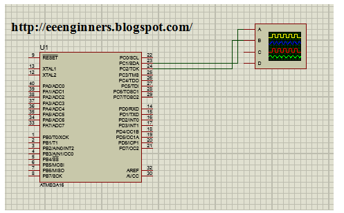
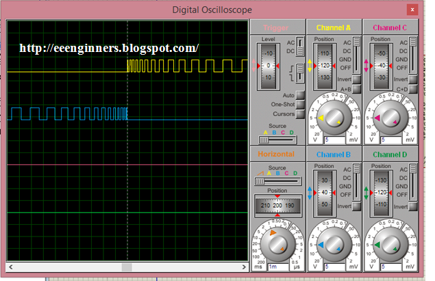
Timer:
·
Timer in simple terms
is a register.
·
It can hold 8 or 16 bit
data.
·
There are 3 timers i-e
timer0,timer1 & timer2.
·
Timer0 & timer2 are
8 bit while timer1 is 16 bit.
·
We have used used
timer0 & timer2 to generate PWM i-e one timer for one set of H-bridge
switches.
8
Bit Timer Registers:
There are 3 different registers for 8
bit timers:
1.
TCCR(Timer
Counter Control Register):
·
It selects the mode of
operation, clock source & prescalars for the timer.
2.
TCNT(Timer
Counter Register):
It holds the value of
timer count.
3.
TIMSK(Timer/Counter
Interrupt Mask Register):
It contains interrupt
control bits for all 3 timers.
Code:
#include
<mega16.h>
#include
<delay.h>
unsigned char display
[100]
={0xfa,0xf9,0xf8,0xf7,0xf6,0xf4,0xf2,0xf0,0xee,0xeb,0xe8,0xe5,0xe2,0xdf,0xdb,0xd7,0xd3,0xcf,0xca,0xc6,0xc1,0xbc,0xb6,0xb1,0xab,0xa5,0x9f,0x99,0x93,0x8d,0x86,0x7f,0x78,0x71,0x6a,0x63,0x5c,0x55,0x4d,0x46,0x3e,0x37,0x2f,0x27,0x1f,0x18,0x10,0x08,0x00,0x00,0x08,0x10,0x18,0x1f,0x27,0x2f,0x37,0x3e,0x46,0x4d,0x55,0x5c,0x63,0x6a,0x71,0x78,0x7f,0x86,0x8d,0x93,0x99,0x9f,0xa5,0xab,0xb1,0xb6,0xbc,0xc1,0xc6,0xca,0xcf,0xd3,0xd7,0xdb,0xdf,0xe2,0xe5,0xe8,0xeb,0xee,0xf0,0xf2,0xf4,0xf6,0xf7,0xf8,0xf9,0xfa};
interrupt [TIM0_OVF]
void timer0_ovf_isr(void)
{ static int i=1;
PORTC.1=~PORTC.1;
TCNT0= display[i];
i++;
if(i==98)
{ i=1;
PORTC.1=0;
TCCR0=0x00;
TCCR2=0x02;
TCNT2=0xfa;
TIMSK=0x40;
#asm("sei")
}
}
interrupt [TIM2_OVF]
void timer2_ovf_isr(void)
{ static int j=1;
PORTC.2=~PORTC.2;
TCNT2= display[j];
j++;
if(j==98)
{ j=1;
PORTC.2=0;
TCCR2=0x00;
TCCR0=0x02;
TCNT0=0xfa;
TIMSK=0x01;
#asm("sei")
}
}
void main(void)
{
DDRC=0xff;
PORTC=0x00;
TCCR0=0x02;
TCNT0=0xfa;
TIMSK=0x01;
#asm ("sei")
while(1)
{
}
}


Hello please guide me to implement the code for feedback and enable/disable option for this code
ReplyDelete